

Key Takeaways
- Conventional commissioning tests can verify individual protection functions, while still missing a number of blind spots leading to a system trip under load.
- Phasor analysis is a technique engineers use to compare actual current and voltage measurements with expected behavior, making sure a system performs the way it was designed to under live-load.
- Our experts say, “Don’t wait for the trip!” Using phasor analysis proactively reduces the risk of unexpected downtime and costs.
For birthdays and anniversaries, everyone loves a good surprise! But a newly commissioned substation or industrial facility? That is one place where no one wants the unexpected.
Yet surprises still happen. Even after a skilled project team has followed its commissioning procedures, checked the drawings, and tested the protection system, hidden wiring and configuration errors can survive long enough to cause trouble. Everything appears status quo under a light load. Then production ramps up, the protection system trips, and a quiet commissioning oversight becomes a very loud (and expensive) operational problem.
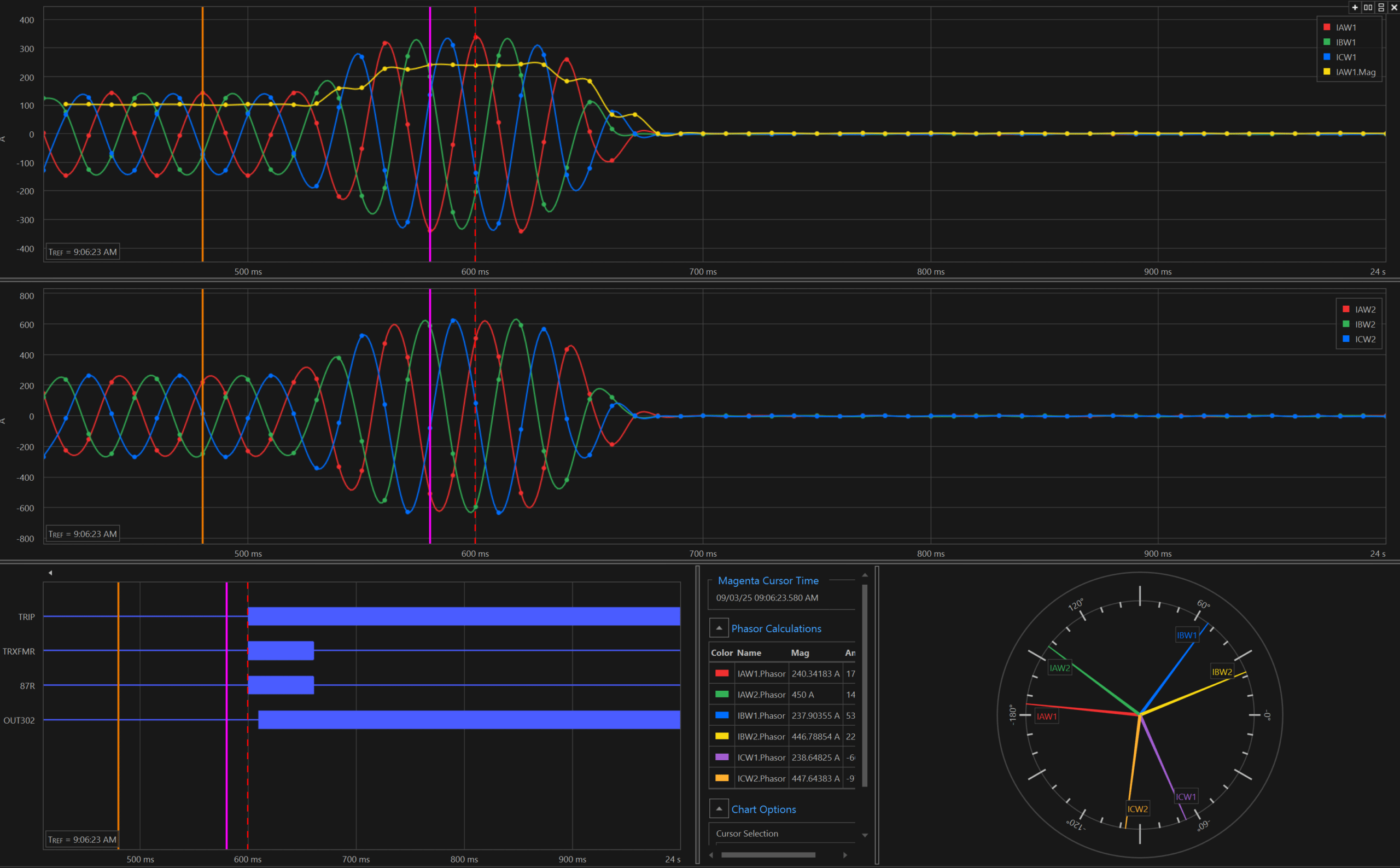
Live-load phaser analysis provides an additional layer of verification before project handoff. By comparing the magnitude and phase relationships of current and voltages recorded by protective relays, engineers can confirm that the installed system behaves as the drawings, transformer connections, and relay settings intend for them to. This process can expose defects during commissioning rather than after an unexplained trip.
Think of it as a final reality check. The individual components passed their tests, but does the complete system actually make sense when real power begins to flow?
Blind Spots in Conventional Site Acceptance Testing
Conventional electrical commissioning commonly includes secondary-injection testing to verify relay logic and protection functions. These tests are essential. They confirm that the relay responds correctly when it receives a simulated input. But, unless the commissioning plan also confirms the complete protection and measurement chain under actual load, certain installation, polarity, configuration, and scaling error may remain undetected. A relay may perform exactly as programmed while receiving incorrect information from the field. A current transformer may have the wrong polarity. Two phases may be transposed. A ratio compensation setting may be incorrect. In other words, the system can pass individual tests and still be headed toward a trip.
One common blind spot involves current transformer, or CT, wiring. Some transformer connections are enclosed within oil-filled tanks, putting them well beyond the reach of a visual inspection after assembly. If an internal connection does not match the design and drawings, field contractors may unknowingly complete the external wiring based on incorrect information.
Under light commissioning loads, the problem may keep a low profile. An incorrect polarity or phase relationship can produce an abnormal differential quantity that remains below the protective relay’s operating threshold. As the facility load increases, the apparent imbalance also grows and may eventually cause the relay to do exactly what it was designed to do: trip.

Picture a water tank with flow meters at the inlet and outlet. If one meter is installed backward, the monitoring system may see an imbalance even though the water is flowing normally. At a low flow rate, the discrepancy might remain below the alarm threshold. Turn up the flow, and the same installation suddenly sets off alarms and triggers a shutdown.
Electrical protection systems can behave in much the same way. Light load can let a hidden defect fly under the radar. Full load is far less forgiving.
Phasor Analysis Reveals What Conventional Testing Misses
Wiring is not the only place problems hide. Relay configuration creates another opportunity for an otherwise successful commissioning process to go sideways.
A single incorrect CT ratio, transformer rating, phase compensation, setting or scaling factor can prevent a protective relay from correctly reconciling its measured inputs. The individual relay functions may have passed simulated testing, yet the complete system may not perform as intended when energized and carrying load.
This is where live-load phaser analysis earns its place in the commissioning process. Depending on the application, the review may include:
- Phase rotation and phase identification
- Current and voltage magnitudes and angles
- CT and voltage-transformer polarity
- Expected phase shifts across transformers
- Relay metering and scaling
- Differential and restraint quantities
- Agreement among field conditions, design drawings, and relay settings
In other words, phasor analysis helps answer a basic but critical question: Does the energized system behave like the system we designed?
A Real-World Lesson: Uncovering the Hidden Issue
The value of this approach became clear during a critical grid upgrade for a municipal public works department whose system relies on a 25 Hz power supply.
To provide backup power, the client installed three frequency converters. The units operated successfully under light load. Then, at approximately 50 percent of their intended operating load, the entire system tripped and the facility went dark.
After conventional troubleshooting efforts did not reveal the cause, MSB’s engineers stepped in and conducted a targeted phasor analysis. By examining the captured internal waveform, the team identified a polarity discrepancy in the transformer wiring. The internal connections did not agree with the manufacturer’s drawings that the field contractors followed.
The broader investigation uncovered similar discrepancies affecting five transformers supplied by two manufacturers. In short, the conventional tests had not exposed the issue. The phasor relationships told the real story.

Preemptive Phasor Analysis – Don’t Wait for the Trip
Phasor analysis is commonly used after an event, when engineers download relay records and work backward to determine what caused the system to operate. Incorporating it into site acceptance testing shifts the process from reactive troubleshooting to proactive verification.
Moving phasor analysis into site acceptance testing turns it into a proactive verification step. Once the equipment is energized and carrying enough stable load to generate meaningful measurements, engineers can compare the actual electrical relationships with the expected system model.
When planned from the beginning, this review can often be incorporated into the commissioning schedule without materially delaying the project – also minimizing the risk of unforeseen additional costs.
The data, however, do not interpret themselves. Phasor analysis is not simply a matter of opening a data file. It requires an engineer who understands both the design intent and the behavior of the energized system.
Looking to the Future
The need for this additional verification is growing as industrial and municipal facilities adopt more complex power architectures. Many facilities now operate multiple generators, transformers, converters, utility sources, or distributed energy resources to improve resilience and provide operational flexibility.
These systems offer meaningful benefits, but they also create more operating configurations. And, ultimately, more opportunities for a polarity, scaling, wiring, or programming error to cause problems.
Live-load phasor analysis provides a practical way to confirm that the physical installation, relay configuration, and engineering design agree before the system is placed into full service.
MSB is incorporating upfront phasor verification into its engineering design and quality-assurance consulting services.
By adding this focused check during commissioning, project teams can reduce uncertainty at handoff, protect capital investments, lower the risk of avoidable downtime, and ensure the only surprises they encounter are the ones worth celebrating.